ASTM D850 Standard Test Method for Distillation of Industrial Aromatic Hydrocarbons and Related Materials
6. Apparatus
6.1 Distillation Flask - A standard 200-mL side-tube, heat-resistant glass distillation flask as shown in Fig. 1, conforming to the following dimensions:
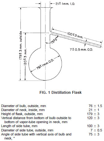
The flask does not comply with Flask C of Specification E 133.
6.2 Temperature Measurement Devices:
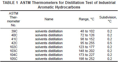
6.2.1 Manual Distillation Thermometer- The ASTM Solvents Distillation Thermometer used in the test shall be as prescribed in the specifications for the material being tested. If no thermometer is specified in the material specification, select one from Table 1 with the smallest graduations that will cover the entire distillation range of the material being tested. Table 1 lists several ASTM solvents distillation thermometers which are suitable for testing industrial aromatic hydrocarbons, and which meet the requirements of Specification E 1.
6.2.2 Automatic Distillation Temperature Sensor - Temperature measurement systems using thermocouples or resistance thermometers, otherwise referred to as the "temperature measuring devices", must exhibit the same temperature lag and accuracy as the equivalent mercury glass thermometer. Confirmation of the calibration of these temperature sensors is to be done at regular intervals. This may be accomplished as prescribed in Test Method E 220, or some similar means using a precision resistance decade box. Another technique is to distill pure toluene and compare the temperature indicated by the thermocouple or resistance thermometer with that shown by the thermometer. When installing a new automatic distillation analyzer, a toluene sample with a known distillation range of approximately 1.0°C must be used to verify the dry point and distillation range. It is recommended that such a material be used when replacing a temperature measuring device. Alternatively a material of known distillation range and dry point may be used when replacing a temperature measuring device.
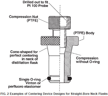
6.2.2.1 Automatic Distillation Temperature Sensor Centering Device - The temperature sensor shall be mounted through a snug-fitting device designed to mechanically center the sensor in the neck of the flask. The use of a cork or silicone stopper with a hole drilled through the center is not acceptable for this purpose. Examples of acceptable centering devices are shown in Fig. 2.
6.2.2.2 The electronic circuitry or algorithms, or both, used shall include the capability to simulate the temperature lag of a mercury-in-glass thermometer. For that reason the known toluene sample with a distillation range of approximately 1.0°C must be used to verify the algorithm and dampening software.
6.2.2.3 Alternatively, the sensor can also be placed in a casing with the tip of the sensor covered, so that the assembly, because of its adjusted thermal mass and conductivity, has a temperature lag similar to that of a mercury-in-glass thermometer.
NOTE 1 - In a region where the temperature is changing rapidly during the distillation, the temperature lag of a thermometer can be as much as 3 s.
6.3 Condenser and Cooling Bath:
6.3.1 Manual Distillation Condenser and Cooling Bath:
6.3.1.1 The manual distillation condenser and cooling bath shall be as specified in Section 5, and Fig. 1 of Specification E 133.
6.3.1.2 As an alternative, the condenser tube may consist of a straight glass tube 600 to 610 mm in length and 12 mm in inside diameter, of standard wall thickness (about 1.25 mm) with the exit end cut off square and ground flat. It shall be set in a cooling trough so that at least 380 mm of the tube is in contact with the water. Clearance between the condenser tube and any parallel side of the trough shall be not less than 19 mm. The water in the cooling trough shall be maintained at 10 to 20°C. This may be done by adding ice to the water or by circulating chilled water through the trough. The trough shall be so mounted that the condenser tube is set at an angle of 75° with the vertical.
6.3.2 Automatic Distillation and Cooling Bath - The automatic distillation and cooling bath shall be as specified in Section 5, Fig. 2 of Specification E 133.
6.4 Distillation Receiver:
6.4.1 Manual Distillation Receiver - A graduate of the cylindrical type, of uniform diameter, with a pressed or molded base and a lipped top. The cylinder shall be marked to contain 100 mL, and the 0 to 100 mL receiver portion shall be not less than 178 nor more than 203 mm in length. It shall be graduated in single millilitres and each fifth mark shall be distinguished by a longer line. It shall be numbered from the bottom up at intervals of 10 mL. The overall height of the receiver shall not be less than 248 nor more than 260 mm. The graduations shall not be in error by more than 1 mL at any point on the scale. The bottom 1-mL graduation may be omitted. The receiver complies with Section 9, Graduate B Fig. 4, of Specification E 133.
6.4.2 Automatic Distillation Receiver - A receiver to be used with measurements in accordance with the instrument manufacturer and conform to the physical specifications described in this section, with the exception of the graduations.
6.4.2.1 Automatic Distillation Level Follower - For automatic apparatus, the level follower or recording mechanism of the apparatus will have a resolution of 0.1 mL with an accuracy of more or less 1 mL. The calibration of the assembly should be confirmed according to the manufacturer's instructions at regular intervals. The typical calibration procedure involves verifying the output with the receiver containing 5 and 100 mL of material respectively.
6.5 Support for Flask - A sheet of 3 to 6-mm hard insulation board approximately 152 mm square with a circular hole in the center, supported on a circular metal shield enclosing the bunsen burner, and approximately 50 mm higher than the top of the burner. For tests of benzene and toluene, the hole shall be 25 mm in diameter; for tests of materials boiling above toluene but mostly below 145°C, the hole shall be 38 mm in diameter, and for higher boiling materials, it shall be 50 mm in diameter.
6.6 Heater:
6.6.1 Manual Distillation Heater - An electric heater or a bunsen burner, fully adjustable and capable of giving sufficient heat to distill the product at the required rate. When a bunsen burner is used, as described in 7.1 and Fig. 1 of Specification E 133, the burner shall be adjusted so as to produce an entirely blue flame. (Warning - Superheating of the flask can cause erroneous results and is more likely to occur with electric heaters than with bunsen burners as heat sources. This problem is discussed in the section on Preparation of Apparatus in Test Method D1078.)