12. Procedure
12.1 Manual Apparatus:
12.1.1 Establish the cooling bath temperature at -34 more or less 0.5°C
12.1.2 Place the insulating ring (see 6.1.4) on the bottom of the jacket (see 6.1.3). If spacers (see 6.1.5) are not mounted on the insulating ring (see 6.1.4), position them approximately 15 and 75 mm above the bottom of the test jar (see 6.1.2).
12.1.3 Pour the filtered specimen (see Section 9) into the clean and dry test jar to the mark (45 mL).
12.1.4 Close the test jar with the stopper (see 6.1.7) carrying the pipet with filter unit (see 6.1.8) and the appropriate thermometer (see 6.1.9). Use a low-range thermometer if the expected CFPP is below -30°C. Thermometers shall not be changed during the test. Adjust the apparatus in such a way that the bottom of the filter unit (see 6.1.8.2(e)) rests on the bottom of the test jar, and position the thermometer so that its lower end is 1.5 more or less 0.2 mm above the bottom of the test jar. Take care to ensure that no part of the thermometer is not in contact with the side of the test jar or the filter body.
NOTE 7 - The precise positioning of the thermometer in the test jar is a critical parameter of this test method. The position of the lower end of the thermometer above the bottom of the test jar can be indirectly measured by marking the stem of the thermometer flush with the stopper (see 6.1.7) when the lower end of the thermometer is just touching the bottom of the test jar, and then pulling the thermometer up such that the reference line is 1.5 more or less 0.2 mm above the top of the stopper.
12.1.5 If the jacket is not an integral part of the cooling bath, place the jacket vertically to a depth of 85 more or less 2 mm in the cooling bath (see 6.1.10), which is maintained at the temperature of -34 more or less 0.5°C.
12.1.6 Insert the test jar assembly in a stable vertical position into the jacket.
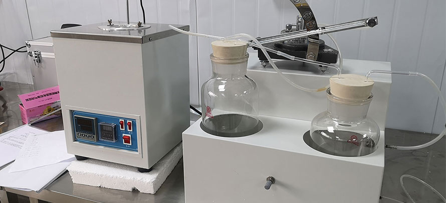
12.1.7 With the stopcock (see 6.1.11) open to atmosphere, connect the pipet to the vacuum system (see 6.1.12 and 6.1.13) by means of flexible tubing attached to the stopcock (see Fig. 1). Switch on the vacuum source and regulate to ensure an air flow rate of 15 L/h in the vacuum regulator (see 6.1.13). Before starting a test, check that the U-tube manometer indicates a 200 more or less 1 mm of water depression (2 more or less 0.05 kPa).
12.1.8 Start the test immediately after inserting the test jar assembly into the jacket, but if the cloud point of the sample is known, it is permitted to wait until the specimen has cooled to a temperature of not less than 5°C above its cloud point.
12.1.9 When the specimen temperature reaches a suitable integer value, turn the stopcock (see 6.1.11) so that the filter assembly is connected to the vacuum source, causing the specimen to be drawn through the wire mesh into the pipet; simultaneously start the stopwatch.
12.1.10 When the specimen reaches the mark on the pipet, stop the stopwatch and turn the stopcock to its initial position to vent the pipet and so allow the specimen to return to the test jar.
12.1.11 If the time taken to reach the mark exceeds 60 s on the first filtration, abandon the test and repeat it on a fresh portion, starting at a higher temperature.
12.1.12 Repeat the operations (see 12.1.9 to 12.1.10) for each 1°C decrease of the specimen temperature until the temperature is reached at which the pipet is not filled to the 20 mL mark within 60 s. Record the temperature at which this last filtration was commenced as CFPP (see Section 13).
NOTE 8 - A small minority of samples may exhibit anomalous aspiration behavior, which can be detected by examining the observed aspiration times. This behavior is marked by an unexpected reduction in the time taken to fill the pipet, after which aspiration time again continues to increase progressively, until the failure limit of 60 s is reached.
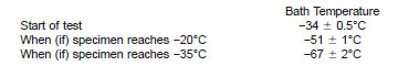
12.1.13 If the filter has not plugged when the temperature of the specimen reaches -20°C, continue the test by using a second cooling bath maintained at -51 more or less 1°C, quickly transferring the test jar and filtration assembly to a new jacket placed on the second cooling bath. Alternatively, for single bath apparatus, adjust the refrigeration unit to -51 more or less 1°C. The new temperature must be reached within 2 min 30 s of the adjustment. Repeat the operations 12.1.9 to 12.1.10 to each 1°C decrease of the specimen temperature.
12.1.14 If the filter has not plugged when the temperature of the specimen reaches -35°C, continue the test by using a third cooling bath maintained at -67 more or less 2°C by quickly transferring the test jar and filtration assembly to a new jacket placed on the second cooling bath. Alternatively, for single bath apparatus, adjust the refrigeration unit to -67 more or less 2°C. The new temperature must be reached within 2 min 30 s of the adjustment. Repeat the operations 12.1.9 to 12.1.10 at each 1°C decrease of the specimen temperature.
12.1.15 If the filter has not plugged when the temperature of the specimen reaches -51°C, discontinue the test (see Section 13).
12.1.16 If, after cooling in accordance with 12.1.12, 12.1.13, and 12.1.14, the specimen fills the pipet to the mark in less than 60 s, but does not flow back completely into the test jar when the pipet is vented to atmosphere through the stopcock (see 6.1.11) before the start of the next aspiration, record the temperature at the commencement of the filtration as the CFPP (see Section 13).
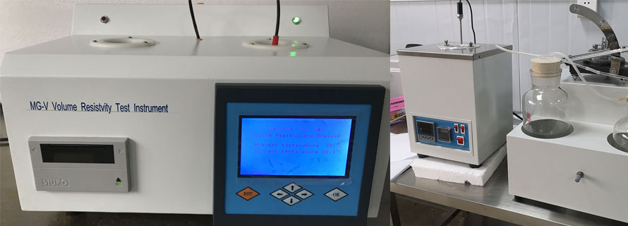
12.2 Automated Apparatus:
12.2.1 Check that the cooling bath is operating and has reached the temperature required as specified in the manufacturer's instructions.
12.2.2 Pour the filtered specimen (see Section 9) into the clean and dry test jar to the 45 mL mark.
12.2.3 Close the test jar with the stopper (see 6.1.7) carrying the pipet with filter unit (see 6.1.8) and the platinum resistance thermometer. Adjust the apparatus in such a way that the bottom of the filter unit (see 6.1.8.2(e)) rests on the bottom of the test jar, and position the thermometer so that its lower end is 1.5 more or less 0.2 mm above the bottom of the test jar. Take care to ensure that no part of the thermometer is in contact with the side of the test jar or the filter body.
NOTE 9 - The precise positioning of the thermometer in the test jar is a critical parameter of this test method. The position of the lower end of the thermometer above the bottom of the test jar can be indirectly measured by marking the stem of the thermometer flush with the stopper (see 6.1.7) when the lower end of the thermometer is just touching the bottom of the test jar, and then pulling the thermometer up such that the reference line is 1.5 more or less 0.2 mm above the top of the stopper.
12.2.4 If necessary, reconnect the pipet to the vacuum system. Switch on the vacuum source and regulate to ensure an air flow rate of 15 L/h in the vacuum regulator. Check that the U-tube manometer (if used) indicates a 200 more or less 1 mm depression (2 more or less 0.05 kPa) or that the electronic vacuum regulator indicates a pressure of 2 more or less 0.05 kPa.
12.2.5 Press the start button immediately after insertion of the test jar assembly. If the cloud point is known, aspiration of the specimen through the filter may be set to start when it has cooled to a temperature not less than 5°C above the cloud point. The apparatus will carry out the test procedure filtering the specimen at each 1°C decrease if temperature and measuring the filtering time. If the time to reach the 20 mL mark exceeds 60 s on the first filtration, the test is to be abandoned and repeated on a fresh specimen starting at a higher temperature. The apparatus will record the first temperature at which the specimen fails to reach the 20 mL mark in less than 60 s or fails to flow back into the test jar when the vacuum is cut off as CFPP (see Section 13). The test will be discontinued if the specimen reaches -51°C without plugging (see Section 13). During the procedure, the apparatus will automatically change the cooling bath temperature as indicated below.
NOTE 10 - A small minority of samples may exhibit anomalous aspiration behavior, which can be detected by examining the aspiration times recorded in the test printout for signs of an unexpected reduction in the time taken to fill the pipet, after which aspiration time again continues to increase progressively until the failure limit of 60 s is reached.
12.2.6 If the automated CFPP apparatus used does not incorporate a lower light sensor, it shall only be used if the test sequence is observed as in the manual procedure (see 12.1.16), so that any fuels not flowing back into the test jar as described are detected and reported accordingly.