ASTM D5707 Standard Test Method for Measuring Friction and Wear Properties of Lubricating Grease Using a High-Frequency, Linear-Oscillation (SRV) Test Machine
9. Procedure
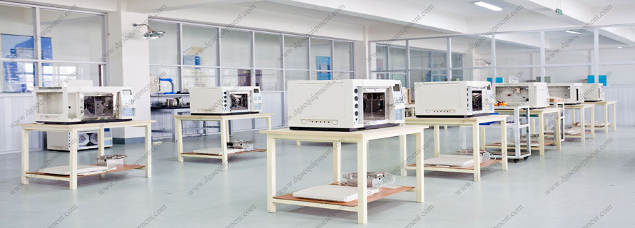
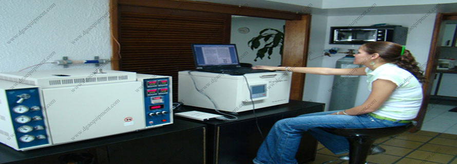
9.1 Procedure for All SRV Models - SRV III, IV, and V models are fully computer-controlled and allow automated tests.
9.1.1 Using solvent resistant gloves, clean the test ball and disk by wiping the surfaces with laboratory tissue soaked with the cleaning solvent. Repeat wiping until no dark residue appears on the tissue. Immerse the test ball and disk in a beaker of the cleaning solvent under ultrasonic vibration for 10 min. Dry the test ball and disk with a clean tissue to ensure no streaking occurs on the surface.
9.1.2 Ensure that the test load unit is in the release position (refer to operating manual for details).
9.1.3 Place a small amount (approximately 0.1 g to 0.2 g, the size of a pea) of lubricating grease to be tested on the cleaned lower test disk in an area such that overlapping with previous wear scars will not occur. Alternatively, place the grease caliper with 1.5 mm in height on the cleaned disc. Fill the opening of the grease caliper with grease. Remove any excess grease by means ofa spatula. Remove the grease caliper by lifting it upwards.
9.1.4 Place the cleaned test ball on the top and in the middle of the lubricating grease specimen so that the grease makes a circular symmetric pad between the ball and disk.
9.2 Procedure for SRV III, IV, and V Models:
9.2.1 Open the Assistant for starting a test in the SRV control software. Select the created set-point profile and, if necessary (for example, SRV V), the data logger configuration and proceed through the Assistant until the pre-load has been applied.
9.2.2 Then set the test load unit to 50 N and release and retighten the ball and disk clamps to a torque of 2.5 Nm.
9.2.3 The heater control starts automatically and heats up to the pre-set and desired temperature. 50 °C, 80 °C, or 120 °C.
9.2.4 Follow the directions in the Assistant for starting a test in the SRV control software until the automated test run mode (waiting for reaching start conditions) is started. The test starts automatically when the pre-set delay (for example, 300 s) has expired. The test can also be started manually. The test machine will automatically stop.
9.3 Procedure for SRV I and II Models:
9.3.1 Ensure the machine is unloaded (indicated by a load reading of −13 N or −14 N) and carefully place the disk containing the lubricating grease specimen and test ball on the test area platform.
9.3.2 Tighten both the ball and disk clamps until resistance to tightening just begins. Load unit to 100 N and tighten the ball and disk clamps to a torque of 2.5 N·m. Reduce the load to 50 N for break-in.
9.3.3 Turn on the heater control and set to the desired temperature.
9.3.4 When temperature has stabilized, turn on the chart recorder paper feed, and lower the recording pens. Depress the drive start toggle switch until the timer begins to count and then adjust the stroke amplitude knob to 1.00 mm.
NOTE 8 - Stroke should be checked periodically by measuring the wear track length minus the ball scar diameter. The difference must be smaller than +/- 10 % of the set stroke.
9.3.5 When the digital timer reaches 30 s, increase the load to 200 N on the slow ramp speed setting and run at that load for 2 h +/- 15 s. The test machine will automatically stop.
9.3.6 At the end of the test, turn off the heater control, turn power back on, and reduce the load to -13 N or -14 N for disassembly.
NOTE 9 - Power automatically turns off at the end of the test.
9.4 Evaluation Procedure:
9.4.1 Remove and clean the test ball and disk in accordance with 9.1.
9.4.2 Place the test ball on a suitable holder and by means of a microscope, measure to the nearest 0.005 mm the minimum scar width and again at 90° to the first measurement. Measure the minimum coefficient of friction values from the chart recorder graph. Although not specifically part ofthe procedure, when additional wear analysis or the wear volume is required, perform a profilometric trace across the wear scar on the test disk in accordance with the profilometer manufacturer's instructions.
NOTE 10 - Criteria for using the wear volume are stated in Test Method D6425 and for calculating the wear volume in Practice D7755 or DIN 51834, Part 3.