8. Sampling
8.1 Denatured ethanol can be sampled into an open container since a vapor pressure of less than 21 kPa (3 psi) is expected. Refer to Practice D4057 for instruction on manual sampling from bulk storage into open containers. Stopper container immediately after drawing the sample.
8.2 Transfer an aliquot of the sample into a septum vial and seal. Obtain the test sample for analysis directly from the sealed septum vial, for either manual or automatic syringe injection.
9. Preparation of Apparatus
9.1 Install and condition column in accordance with manufacturer's or supplier's instructions. After conditioning, attach column outlet to flame ionization detector inlet and check for leaks throughout the system. When leaks are found, tighten or replace fittings before proceeding.
9.2 Adjust the carrier gas flow rate so that the average linear gas velocity, at the initial temperature of the run, is between 21 and 24 cm/s, as determined by the following equation:
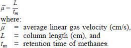
Flow rate adjustment is made by raising or lowering the carrier gas pressure (head pressure) to the injector.
9.3 Adjust the operating conditions of the gas chromatograph (Table 1) and allow the system to equilibrate.
9.4 Linearity - The linearity of the gas chromatograph system shall be established prior to the analysis of samples.
9.4.1 The split ratio used is dependent upon the split linearity characteristics of the particular injector and the sample capacity of the column. The capacity of a particular column for a sample component is proportional to the amount of liquid phase (loading or film thickness) and the ratio of the column temperature to the component boiling point (vapor pressure). Overloading of the column may cause loss of resolution for some components and, since overloaded peaks are skewed, variance in retention times. This can lead to erroneous component identification. During column evaluations and split linearity studies, be aware of any peaks that may appear front skewed, indicating column overload. Note the component size and avoid conditions leading to this problem during actual analysis. Refer to Practice E 594 for further guidance.
9.4.2 Splitting injector linearity must be established to determine proper quantitative parameters and limits. Use a standard mixture of known mass percentages of ethanol, methanol, and 10 to 20 pure hydrocarbons, covering the boiling range of this test method. The determined mass percent for each component shall match the gravimetric known concentration within +/- 3 % relative.
9.4.3 The linearity of the flame ionization detector (FID) should shall be verified. Refer to Prachtice E 594 for suggested prockedure. A plot of the peak areas versus ethanol concentration for prepared standards in the concentration range of interest should be linear. If the plot is not linear, either the split ratio shall be increased or the detector range must be made less sensitive.
10. Calibration and Standardization
10.1 Identification - Determine the retention time of ethanol and methanol by injecting amounts of each, either separately or in known mixtures, in proportions expected in the final blend using n-heptane as the solvent.
10.2 Calibration - Typical mass relative response factors for the components of interest are found in Table 2. These response factors shall be determined by analyzing a standard that has been blended according to Practice D 4307. This standard is comprised of the proportions of ethanol and methanol expected in the sample using n-heptane in place of the denaturant. A typical standard blend would be >96 % ethanol, 0.1 % methanol and 3.9 % n-heptane. Calculate the mass relative response factor according to Practice D4626.