6. Apparatus
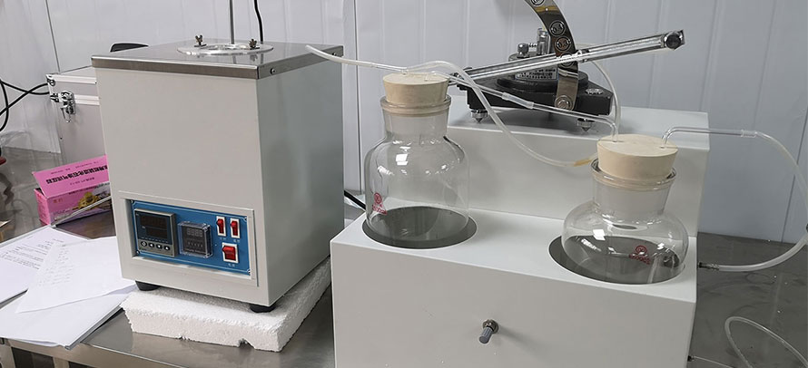
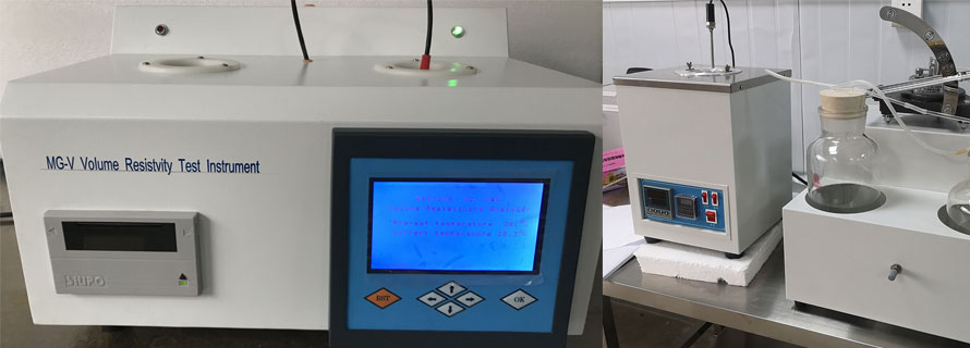
6.1 High-Temperature High-Shear (HTHS) Viscometer, consisting of several viscometer cells in a temperature-controlled block and including means for controlling and measuring temperature and applied pressure and for timing the flow of a predetermined volume of test oil. Each viscometric cell contains a precision glass capillary and means for adjusting the test oil volume to the predetermined value.
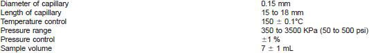
6.1.1 The HTHS viscometer has the following typical dimensions and specifications:
6.1.2 The thermometer for measuring the temperature of the block is a pre-set digital resistance thermometer. The accuracy of this thermometer may be checked by means of a special thermowell and calibrated thermometer whose accuracy is +/- 0.1°C or better. See manufacturer's recommendations for procedure.
7. Reagents and Materials
7.1 Newtonian Oils, having certified viscosities of 2 to 7 mPa•s at 150°C. See Table 1.
7.2 Non-Newtonian Reference Sample, having a certified viscosity at 150°C and 10(6)s(−1).
7.3 Carbon Dioxide or Nitrogen Cylinder, with reducer valve having a maximum pressure of at least 500 psi (3500 Pa).
8. Sampling
8.1 A representative sample of test oil, free from suspended solid material and water, is necessary to obtain valid results. When the sample is suspected to contain suspended material, filter with about 10-µm filter paper.
9. Calibration and Standardization
9.1 Calibration:
9.1.1 The volume and capillary diameter of each viscometric cell is provided by the manufacturer, and the flow time, to, corresponding to an apparent shear rate at the wall of 1.4 x 10(6)s(−1) is calculated by the manufacturer using the following equation:
to = 4V/1.4*10(6)πR3
where symbols are defined as in 3.1.1.
9.1.2 Using a minimum of four Newtonian calibration oils covering the viscosity range from 2 to 5 mPa•s (cP) at 150°C, determine the relationship between pressure and flow rate. The pressure should be adjusted for each calibration oil such that the flow time is within +/- 20 % of the nominal flow time, to. Make three determinations for each oil in each cell.
9.1.2.1 The following relationship can be used to express the data:
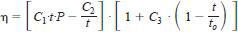
where:
η = viscosity, mPa•s,
t = flow time, s,
P = pressure, kPa or psi, and
C1, C2, C3 = coefficients specific to each viscometer cell.
9.1.2.2 Coefficient C1 is specific to the units in which pressure is expressed, as well as to each cell. Coefficient C2 will be essentially constant over the relatively narrow range of shear rates and viscosities of interest in measurement of the high-temperature viscosity of automotive engine oil. In more general applications, C2 may not be constant for all values of Reynolds Number.
9.1.2.3 Annex A1 describes the procedure for determining coefficients C1, C2, and C3.
9.2 Stability of Viscosity Calibration - Check the stability of the calibration by running a calibration oil in the same manner as a test oil would be run. This shall be done no less frequently than before each new series of runs and every twentieth run. The non-Newtonian calibration oil should be run at least monthly. The calibration oil viscosity determined in this way must not differ from the standard value by more than the repeatability of the test (see 12.1). If it is out of limits, and if the result is confirmed by a repeat run, look for the source of the trouble, rectify it, and repeat the entire calibration procedure, if necessary. Some possible steps to find the source of the trouble are to check the system thoroughly for faults, including foreign material in the capillary, verify the fidelity of the operating procedure, and accuracy of temperature control, and readout.
9.3 Stability of Temperature Calibration - Check the calibration of the temperature sensor at least once a year using a standardized thermometer inserted in the thermowell in the aluminum block.