ASTM D446 standard specifications and operating instructions for glass capillary kinematic viscometers
4. Nomenclature for Figures
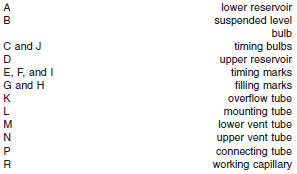
4.1 The figures in the annexes contain letters to designate specific parts of each viscometer. These letters are also used in the text of the standard when reference to the viscometers is given. The more frequently used letters on the figures in the annexes are as follows:

5. Viscometer Holder and Alignment
5.1 All viscometers which have the upper meniscus directly above the lower meniscus (Cannon-Fenske routine in Annex A1 and all in Annex A2) shall be mounted in a constant temperature bath with tube L held within 1° of the vertical as observed with a plumb bob or other equally accurate inspection means. A number of commercially available holders are so designed that the tube L is held perpendicular to the lid of a constant-temperature bath; nevertheless, the viscometer should be tested with a plumb line in order to ensure that the tube L is in a vertical position.
5.1.1 Those viscometers whose upper meniscus is offset from directly above the lower meniscus (all others in Annex A1 and all in Annex A3) shall be mounted in a constant-temperature bath with tube L held within 0.3° of the vertical.
5.2 Round metal tops, designed to fit above a 51-mm hole in the lid of the bath, are frequently cemented on to the Zeitfuchs, Zeitfuchs cross-arm, and Lantz-Zeitfuchs viscometers which then are permanently mounted on the lid of the bath. Also a rectangular metal top, 25 mm x 59 mm, is often cemented on to the Zeitfuchs cross-arm and Zeitfuchs viscometers. Viscometers fitted with metal tops should also be set vertically in the constant-temperature bath with the aid of a plumb line.
5.3 In each figure, the numbers which follow the tube designation indicate the outside tube diameter in millimetres. It is important to maintain these diameters and the designated spacing to ensure that holders will be interchangeable.


