ASTM D3606 Standard Test Method for Determination of Benzene and Toluene in Finished Motor and Aviation Gasoline by Gas Chromatography
10. Configuration of Apparatus and Establishment of Conditions
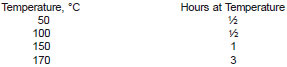
10.1 Conditioning Column - Install Columns A and B as shown in Fig. 1 or Fig. 2 in accordance with the system preferred (5.1). Do not connect the exit end of Column B to the detector until the columns have been conditioned. Pass helium gas through the column at approximately 40 cm3/min. Condition the column at the listed temperatures for the specified time periods.
10.2 Assembly - Connect the outlet of Column B to the detector port. Adjust the operating conditions to those listed in Table 1, but do not turn on the detector circuits. Check the systems for leaks.
10.3 Flow Rate Adjustment:
10.3.1 Column System Setup for Pressure Backflushing (Fig. 1):
10.3.1.1 Open Tap A and B and close C; set the primary pressure regulator to give the desired flow (Table 1) through the column system (at an approximate gage pressure of 205 kPa (30 psi)). Measure the flow rate at the detector vent, sample side. Observe the pressure on gage GC.
10.3.1.2 Close Tap A and open B and C. The pressure reading on gage GA should fall to zero immediately. If not, open the needle valve until the pressure falls to zero.
10.3.1.3 Close Tap B. Adjust the secondary pressure regulator until the reading of gage GC is 3.5 to 7 kPa (0.5 to 1 psi) higher than observed in 10.3.1.1.
10.3.1.4 Open Tap B and adjust the backflush vent control needle valve until the pressure recorded on GA approximates a gage pressure of 14 to 28 kPa (2 to 4 psi).
10.3.1.5 Forward Flow - Open Taps A and C and close Tap B (Fig. 1 B1).
10.3.1.6 Backflush - Close Tap A and open Tap B. (There should be no baseline shift on switching from forward flow to backflush. If there is a baseline shift increase the secondary pressure slightly.) (Fig. 1)
10.3.2 Column System Setup for Valve Backflushing (Fig. 2):
10.3.2.1 Set the valve in the forward flow mode (Fig. 2 B1), and adjust flow control A to give the desired flow (Table 1). Measure the flow rate at the detector vent, sample side.
10.3.2.2 Set the valve in the backflush position (Fig. 2 B2), measure the flow rate at the detector vent, sample side. If the flow has changed, adjust flow control B to obtain the correct flow. (Flows should match to within more or less 1 cm3/min).
10.3.2.3 Change the valve from forward flow to the backflush position several times and observe the baseline. There should be no baseline shift or drift after the initial valve kick that results from the pressure surge. If there is a baseline shift, increase or decrease flow control B slightly to balance the baseline. (A persistent drift could indicate leaks somewhere in the system.)
10.4 Determine Time to Backflush - The time to backflush will vary for each column system and must be determined experimentally as follows. Prepare a mixture of 5 volume % isooctane in n-nonane. Using the injection technique described in 11.4 and with the preferred system (10.3) in the forward flow mode, inject 1 µL of the isooctane - n-nonane mixture. Allow the chromatogram to run until the n-nonane has eluted and the detector signal has returned to baseline. Measure the time in seconds, from the injection until the detector signal returns to baseline between the isooctane and n-nonane peaks. At this point all of the isooctane, but essentially none of the n-nonane, should have eluted. One half of the time determined should approximate the "time to backflush" and should be from 30 to 60 s. Repeat the run, including the injection, but switching the system to the backflush mode at the predetermined "time to backflush". This should result in a chromatogram of isooctane with little or no n-nonane visible. If necessary, make additional runs, adjusting the "time to backflush" until this condition of all the isooctane and little or no n-nonane is attained. The "time to backflush" so established, including the actual valve operations, must be used in all subsequent calibrations and analyses.