6. Apparatus
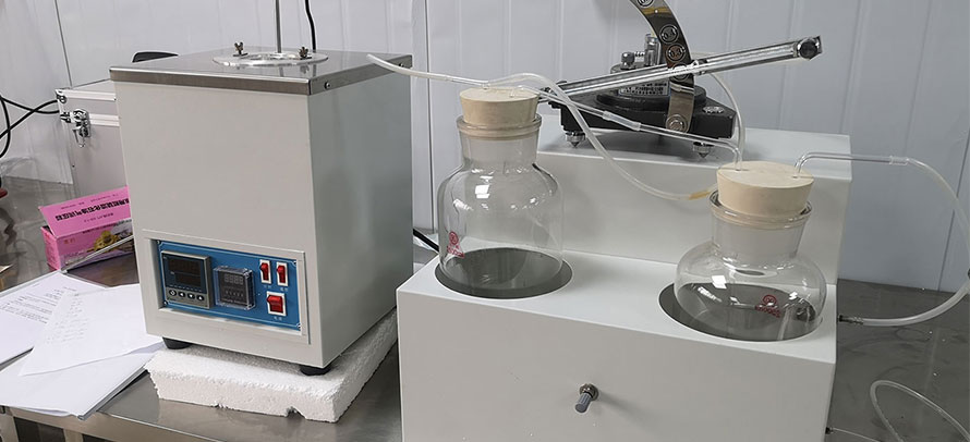
6.1 Distillation at Atmospheric Pressure - All components must conform to the requirements specified as follows. Automatic devices can be employed provided they meet the same requirements. A typical apparatus is illustrated in Fig. 1.
6.1.1 Distillation Flask - The distillation flask shall be of a size that is at least 50 % larger than the volume of the charge. The size of the charge, between 1.0 and 30 L, is determined by the holdup characteristics of the fractionating column, as shown in Table 1 and described in Annex A2. The distillation flask shall have at least one sidearm.
6.1.1.1 The sidearm is used as a thermowell. It shall terminate about 5 mm from the bottom of the flask to ensure its immersion at the end of the distillation. When a second sidearm is present, it can be used for pressure drop detection with a nitrogen bleed or for mechanical stirring, or both.
6.1.1.2 If a magnetic stirrer is used with a spherical flask, the flask shall have a slightly flattened or concave area at the bottom on which the magnetic stirrer can rotate without grinding the glass. In this case, termination of the thermowell shall be off center 40 more or less 5 mm to avoid the magnetic stirring bar. Boiling chips can be used as an alternative to a stirrer.
6.1.1.3 (Warning - While the advantage of visibility in glass distillation flasks is desirable, flasks of glass may become hazardous the larger the charge they contain. For this reason, glass flasks of a volume greater than 10 L are not recommended.)
6.1.2 Heating System - Heating of the flask shall be provided in such a way that full boilup can be maintained at a steady rate at all pressure levels. An electric heating mantle covering the lower half of the flask and having one third of the heat in an element located in the bottom central area and the remaining two thirds in the rest of the hemisphere is recommended. While proportioning controllers are preferred, heat input can be manually adjusted by use of a variable auto transformer on each circuit, the smaller heater being automatically controlled by an instrument sensing the pressure drop of the column as registered in a differential pressure instrument or alternatively by direct measurement of distillation rate.
6.1.2.1 Minimum wattage required to provide full boilup of crude petroleum is approximately 0.125 W/mL of charge. Twice this amount is recommended for quick heat-up.
6.1.2.2 The heat density in the flask heaters is approximately equal to 0.5 to 0.6 W/cm2. This requires the use of nickel reinforced quartz fabric to ensure a reasonable service life.
6.1.2.3 Immersion heaters can be employed in a similar way and have the advantage of faster response, but they are more fragile and require a specially designed flask to ensure that the heating elements remain immersed at the end of the run. When used, their heat density should be approximately equal to 4 W/cm2.
6.1.2.4 The upper half of the flask shall be covered with a mantle to avoid unnecessary heat losses from the upper surface and shall have an electric heater supplying about 0.25 W/cm2 at full-rated voltage.
6.1.3 Fractionating Column - The fractionating column must contain either particulate packing or real plates similar to those whose performance characteristics are summarized in Table 1 and meet the specifications stated in 6.1.3.1 through 6.1.3.4. Table 2 lists current North American suppliers of suitable packings.
6.1.3.1 The internal diameter shall be between 25 and 70 mm.
6.1.3.2 The efficiency shall be between 14 and 18 theoretical plates at total reflux when measured by the procedure described in Annex A1.
6.1.3.3 The fractionating column shall be comprised of a integral glass column and reflux divider totally enclosed in a highly reflective vacuum jacket having a permanent vacuum of less than 0.1 mPa (~10(-6) mm Hg). It shall be essentially adiabatic when tested in accordance with Annex A3.
6.1.3.4 The column shall be enclosed in a heat insulating system, such as a glass-fabric mantle, capable of maintaining the temperature of the outer wall of the glass vacuum jacket equal to that of the internal vapor temperature. To verify this, the vacuum jacket shall have a temperature sensor, such as a thermocouple, soldered to about 6 cm2 of thin copper or brass sheet and fastened to the outer wall of the glass jacket at a level just below the reflux divider.
NOTE 2 - For certain types of columns there is no significant difference in yields and fraction qualities between an uncompensated and a heat-compensated column. In such a case, by mutual agreement between parties concerned, the application of a heated insulating system can be omitted.
6.1.3.5 The adjustable reflux divider shall be located about one column diameter above the top of the packing or topmost plate. It must be capable of dividing the condensate with an accuracy of better than 90 % between the column and the takeoff line over a range of rates from 25 to 95 % of the maximum boilup rate of the column when determined in accordance with Annex A7.
6.1.4 Condenser - The condenser shall have sufficient capacity to condense essentially all the C4 and C5 vapors from the crude at the specified rate, using a coolant temperature of -20°C.
6.1.5 Cold Traps - Two efficient traps of adequate capacity cooled by dry ice and alcohol mixture shall be connected in series to the vent line of the condenser when light hydrocarbons are present, as at the beginning of the distillation. For vacuum distillation, a Dewar-style trap also cooled by dry ice is used to protect the vacuum gage from vapors.
6.1.6 Gas Collector - If uncondensed gas is to be measured, a gas meter can be connected to the outlet of the cold trap but with a calcium chloride drying tube between them to keep moisture from collecting in the traps. When analysis of the gas sample is required, the gas can be collected in an empty plastic balloon of suitable size either in place of the meter or following it. The volume of its contents can be determined by calculation from the rise in pressure after expanding the sample into an evacuated vessel of known volume.
6.1.7 Fraction Collector - This part of the apparatus permits the collection of the distillate without interruption during withdrawal of product from the receiver under atmospheric or reduced pressure. It also permits removal of product from the vacuum system, without disturbing conditions in the column.
6.1.8 Product Receivers - The receivers shall be of suitable size for the quantity of crude petroleum being distilled. The recommended capacity is from 100 to 500 mL. They shall be calibrated and graduated to permit reading to the nearest 1 %.
6.2 Distillation Under Reduced Pressure - In addition to the apparatus listed in 6.1, the apparatus for distillation under reduced pressure shall include the following:
6.2.1 Vacuum Pump - The vacuum system shall be capable of maintaining smooth pressure operation at all pressure levels. It shall have the capacity to draw down the pressure in the receiver(s) from atmospheric to 0.25 kPa (2 mm Hg) in less than 30 s so as to avoid disturbance of the system during emptying of receivers under vacuum. Alternatively, a separate pump can be employed for this purpose.
6.2.2 Vacuum Gage - The point of connection of the vacuum gage to the system shall be as close as practical to the reflux dividing head. The connecting tubing shall be of sufficient diameter to ensure that no measurable pressure drop occurs in the line. In no case shall the vacuum gage connection be near the vacuum pump.
6.2.2.1 All gages shall be carefully protected from condensable vapors, especially water vapor, by a cold trap maintained at the temperature of dry ice.
6.2.3 Pressure Regulator - The regulator shall maintain the pressure in the system essentially constant at all operating pressures. Automatic regulation can be achieved by a device that regulates the demand on the vacuum source. A satisfactory device is a solenoid valve positioned between the vacuum source and a surge tank of at least 10-L capacity. Alternatively, a manual bleed valve can be maintained by a trained operator with a minimum of attention.
6.3 Sensing and Recording Apparatus:
6.3.1 Temperature Sensors - Only temperature measurement systems meeting the requirements of 6.3.1.1 and 6.3.1.2 shall be used.
6.3.1.1 The vapor temperature sensor can be a platinum resistance thermometer, a Type J thermocouple with the junction head fused to the lower tip of the thermowell, or any other device that meets the requirements in this paragraph and 6.3.1.2. The tip of the sensor shall be located above the top of the packing or the topmost glass plate and in close proximity to the reflux divider but not in contact with the liquid reflux. The location of the vapor temperature sensor shall be proved by the test method described in Annex A4. The sensor shall have a cooling time of not more than 175 s, as described in Annex A5.
6.3.1.2 The vapor temperature measuring device shall have an accuracy of 0.5°C or better and be measured with a resolution of 0.1°C or better. The liquid temperature measuring device shall have an accuracy of 1.0°C or better and be measured with a resolution of 0.5°C or better. Temperatures are recorded either manually or automatically.
6.3.1.3 Temperature sensors shall be calibrated as described in Annex A6. Alternatively certified sensors may be used, provided the calibration of the sensor and its associated recording instrument can be traced back to a primary temperature standard. Temperature sensors are calibrated over the full range of temperature (from 0 to 400°C) at the time of first use of the sensor in combination with its associated instrument. Recalibrate when either the sensor or the instrument is repaired or serviced. Verification of the calibration of the temperature sensors is to be made on a regular basis. For vapor temperature sensors, verification at least once a month is recommended and for liquid temperature sensors once every six months. Verification of the calibration of the sensors can be accomplished potentiometrically by the use of standard precision resistance or by distilling a pure compound with accurately known boiling point.
6.3.2 Vacuum Gage - A nontilting McLeod gage or a mercury manometer are primary standards and can be used without calibration when properly used and maintained. A mercury manometer, however, will only be of satisfactory accuracy down to a pressure of about 1 kPa and then only when read with a good cathetometer (an instrument based on a telescope mounted on a vernier scale to determine levels very accurately). Alternatively, a tensimeter or certified electronic sensors may be used, provided the calibration of the sensor and its associated recording instrument can be traced back to a primary pressure standard. Sensors of the diaphragm type have been found satisfactory. Vacuum gages based on hot wires, radiation, or electrical conductivity detectors are not recommended.
6.3.2.1 The gage for measuring subatmospheric pressures shall have an accuracy at least equal to that stated as follows:
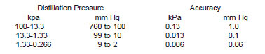
6.3.2.2 Noncertified gages shall be calibrated from a non-tilting McLeod gage or a secondary electronic standard traceable to a primary standard. A basic calibration procedure is described in Annex A6. Recalibrate when either the sensor or the instrument is repaired or serviced. Verification of the calibration of the electronic pressure sensors is to be made on a regular basis. A frequency of at least once a month is recommended. Verification of the calibration of the sensors can be accomplished using the procedures described in Annex A6 or against a certified reference system.
6.3.3 Boilup Rate - The boilup rate is normally controlled by sensing the pressure drop in the column. The pressure drop during operation is measured by means of a manometer or pressure transducer connected between the flask and the condenser. Prevention of condensation in the connecting tube can be accomplished by injecting a very small flow of nitrogen (8 cm3/s) between the pressure drop sensor manometer and the flask (see Fig. 1) or by placing a small water-cooled condenser between the flask and the pressure drop sensor. Alternatively, the boilup rate can be controlled from the measurement of take off rate.