ASTM D2300 Test Method for Gassing of Electrical Insulating Liquids
ASTM D2300 Standard Test Method for Gassing of Electrical Insulating Liquids Under Electrical Stress and Ionization (Modified Pirelli Method)
5. Apparatus
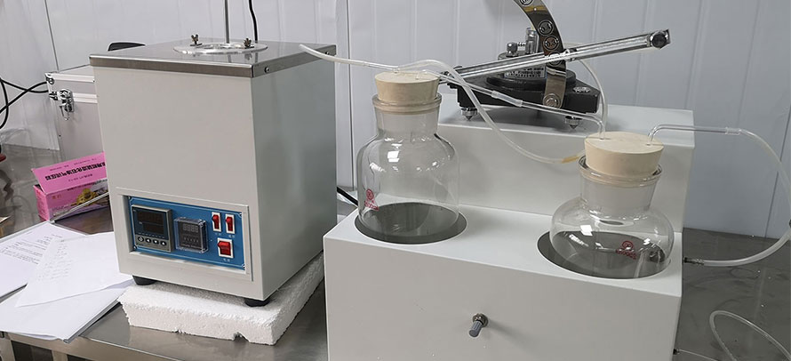
5.1 The apparatus for making gassing tests where the insulating liquid is saturated in the same cell that is used thereafter to electrically stress the insulating liquid is shown in Fig. 1. The apparatus consists of the following:
5.1.1 Gassing Cell and Buret Assembly, as shown in Fig. 1, with dimensions as given in Fig. 2. The gassing cell consists of the following two components:
5.1.1.1 Cell made of borosilicate glass with the part under stress constructed of 16 mm inside diameter and 18 mm outside diameter truebore tubing. This cell has an outer (ground) electrode of painted or plated silver with a vertical slit for observing the insulating liquid level, and a metal conductor band for ground connection.
5.1.1.2 Hollow High-Voltage Electrode made of 10 more or less 0.1-mm outside diameter center-less-ground and polished No. 304 stainless steel seamless tubing and containing an 18-gage stainless steel capillary tubing as a gas passage. The electrode shall be supported and centered by a precision-machined 24/40 recessed TFE-fluorocarbon plug. A 1/8-in. needle valve (E) with gas inlet is on top of the electrode.
5.1.2 Gas Buret (Fig. 1) made of 7-mm outside diameter borosilicate glass tubing with an etched scale, tapered glass joint (G) for connecting to the gassing cell, a bypass stopcock (D), and three glass bulbs, (A, B, and C).
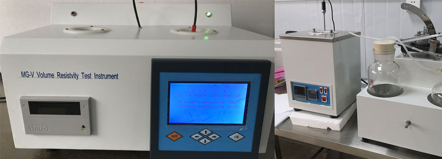
5.1.3 Oil Bath with thermostatic control to maintain the bath at test temperature more or less 0.5°C. The bath shall be equipped with a stirrer, a heating arrangement capable of maintaining the necessary temperature control, a suitable support for the gassing test cell assembly, and a thermometer graduated in 0.1°C divisions. As the test is temperature sensitive, it is important that the calibration is traceable to a standard, such as NIST.
5.1.4 Transparent Safety Shield to protect the operator from contact with high voltage.
5.1.5 High-Voltage Transformer, providing a test voltage having a frequency in the range of 45 to 65 Hz. The transformer and its controlling equipment shall be of such size and design that with the test specimen in the circuit, the voltage wave shape shall approximate a sinoid with both half cycles closely alike. The ratio of peak-to-rms values should be equal to the square root of two within more or less 5 % while maintaining 10 RV more or less 2 %.
6. Reagents and Materials
6.1 Hydrogen, oxygen-free. See Note 1.
6.2 Dibutyl Phthalate, reagent grade.
6.3 2-Propanol, reagent grade.
6.4 Low vapor pressure grease, such as high vacuum silicone grease.
6.5 Unless otherwise indicated, it is intended that all reagents shall conform to the Committee on Analytical Reagents of the American Chemical Society.
NOTE 1 - Hydrogen normally is the saturating gas but other gases, such as nitrogen, carbon dioxide, argon, or air may be used.