ASTM D2112 for oxidation stability of inhibited mineral insulating oil
ASTM D2112 standard test method for oxidation stability of inhibited mineral insulating oil by pressure vessel
A1. ROTATING VESSEL OXIDATION TEST APPARATUS
A1.1 Oxidation Vessel
A1.1.1 Construct the oxidation vessel,6 with lid, cap, and stem, as shown in Fig. A1.1.
A1.1.2 Machine the vessel body and lid from a 3-in. (76-mm) solid copper rod for maximum rate of heat transfer. Give the interior surface a smooth finish to facilitate cleaning. Heavily chrome plate the vessel body and lid. Alternatively, the vessel body and cap may be constructed of 18-8 or 321S12/321S20 Part 1 (BSI) stainless steel to ensure a proper rate of heat transfer.
A1.1.3 Construct the vessel stem of stainless steel, equipped with an inside diameter of 1/4 in. (6.35 mm) and equip with a 1/4-in. needle valve.
A1.1.4 Make the vessel cap (or closure ring) of plated steel.
A1.1.5 The vessel shall withstand a working pressure of 500 psi (3.4 MPa) at 150°C.
A1.1.6 O-ring gaskets, TFE-fluorocarbon resin reinforced silicone, 2 in. (50.8 mm) in inside diameter by 2 3/8 in. (60.3 mm) in outside diameter, or alternatively Buna-N gaskets with the same dimensions.
A1.2 Glass Sample Container
A1.2.1 Construct the glass test specimen container, 175-mL capacity, with copper catalyst coil, of borosilicate glass as shown in Fig. A1.2.
A1.2.2 Cover the top of the test specimen container with a 2-in. (50.8-mm) diameter watch glass. Fire polish the watch glass edges. TFE-fluorocarbon watch glasses are also acceptable.
A1.2.3 The glass test specimen container shall have a sliding fit in the vessel with no excess side clearance. The container alone shall have a maximum wall thickness of 2.5 mm and weigh no more than 100 g.
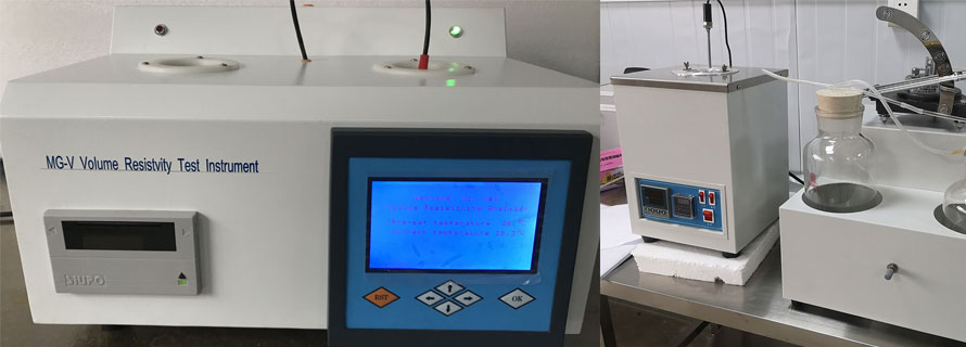
A1.3 Gage
A1.3.1 The range of the gage, recording, (see chart in Fig. A1.3) indicating or equivalent, must span a range from at least 0 to 200 psi (1.4 MPa) and graduated or reading in maximum 5-psi (35-kPa) divisions.
A1.3.2 The accuracy of the gage must be 2 % or less of the total scale interval.
A1.3.3 Mount the recording gages so that the face is perpendicular to the axis of rotation.
A1.3.4 Pressure Measurement System (optional), consisting of electronic pressure transducers, power source, mounting equipment and connecting cables. The rotary transducer couplings can be mounted directly on the vessel stem in place of the standard mechanical pressure recorders. The pressure transducer shall have a span of 0 to 1400 KPa (or 0 to 200 psi or 0 to 14 bar). The accuracy shall be valid over a wide compensated temperature range. The output signal from the transducer can be channeled into a datalogger, microprocessor based recorder, or a computer for data acquisition. The data acquisition package should be capable of logging pressure data and time. The overall system accuracy of the data should be within 2.0 % of the total scale.
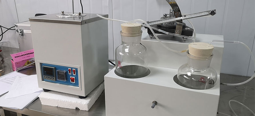
A1.4 Oxidation Bath
A1.4.1 Equip the oxidation bath6 with an efficient stirrer and a suitable device for holding and rotating the vessel axially at an angle of 30° at 100 more or less 5 rpm while submerged in oil to a point at least 1 in. (25.4 mm) below the level of the bath liquid.
A1.4.2 A bath at least 9-in. (230-mm) deep, filled with 8 gal (30.3 L) of heavy bath oil per vessel, has the proper heat capacity. Metal block baths are not satisfactory for this service.
A1.4.3 Provide thermal regulation to maintain the bath within more or less 0.1°C of the test temperature (140°C) for periods as long as 8 h and to ensure sufficient heat is available to bring the bombs to operating temperature within 10 to 15 min.
A1.5 Thermometer
A1.5.1 ASTM Solidification Point Thermometer 96C, having a range from 120 to 150°C, graduated in 0.1°C intervals, described in Specification E 1. Place the thermometer in the bath so that it is submerged to the immersion mark.