8. Preparation of Apparatus
8.1 Cleaning the Lamp - Before each test, clean the top and inside of the wick guide (in the lamp body) with acetone (Warning - Extremely flammable. Vapors may cause flash fire. See A1.3.) using a small test tube brush. Protect the optical filter with a tissue during cleaning. Check the filter for spots after cleaning and if the filter is found to be spotty, clean in place with lens tissue. If necessary, the filter can be removed for cleaning by first removing the lamp and then unscrewing the filter retaining ring. Following the replacement of the lamp, reference fuel checks should be made.
8.2 Wicks and Sample Holders - Only new wicks shall be used. Extract all wicks for at least 25 cycles in a reflux condenser with an equal volume mixture of toluene (Warning - Flammable. Vapor harmful. See A1.4.) and anhydrous methanol (Note 2). (Warning - Flammable. Vapor harmful. May be fatal or cause blindness if swallowed or inhaled. Cannot be made nonpoisonous. See A1.5.) Allow the wicks to dry partially for 5 min, then place them in an oven and dry for 1/2 h at 100 to 110°C. Store in a dessicator until used. Thoroughly wash the sample holder in acetone and dry (Note 3). Then insert a dry wick in the wick tube of the clean sample holder. A piece of thin wire hooked through the end of the wick will allow the wick to be pulled through the tube without twisting. Use a clean razor blade or other sharp instrument to cut off the wick flush with the top of the wick tube (Note 4). Raise the wick by twisting the lower part until the end of the wick protrudes. Then, pull the wick up and remove any twists in the wick by rotating the ends of the wick. Also pull the wick down until the top of the wick is 1/4 in. (6.4 mm) above the tube. Trim any frayed ends from the top of the wick. If the wick has not been cut square, recut and position as outlined above. (Note 5.)
NOTE 2 - If extraction facilities are not available, request supplier to supply wicks that have been extracted.
NOTE 3 - If either fuel or acetone vapors are not removed from the sample holder during the cleaning and drying operations, erroneous ratings can be obtained.
NOTE 4 - Some razor blades have a protective chemical coating which should be removed with a solvent.
NOTE 5 - An alternative method of preparing a wick free of twists and frayed ends utilizes a Wick Trimmer Assembly. The wick trimmer holder is inserted over the top of the wick tube and the long-nosed triceps are inserted through the tube and holder. The wick is grasped and carefully pulled through the tube without twisting. A new clean sharp razor is used to cut the wick at the face of the holder and remove wisps and frayed ends. When the holder is removed, the wick will be at the correct height in the tube. The tube is then inserted into the candle and screwed home. The candle is inserted into the lamp.
8.3 The flame axis of the ASTM-CRC Luminometer lamp must be vertical for proper operation. Adjustable cabinet vibration mounts are provided for this purpose. Adjustment can be checked by a small level positioned on the large flame height adjusting ring. The level of the lamp should be checked in both the front to rear plane and the side to side plane. If at any time the position of the cabinet or the lamp is disturbed, the lamp level must be checked. If the position of the stack thermocouple is disturbed or the thermocouple replaced, the thermocouple should be positioned with the junction exactly on the lamp centerline. The bottom of the thermocouple shield should be exactly 1 in. (25.4 mm) above the wick guide. Suitable gages for this purpose are available from the manufacturer.
8.4 Temperature Measurement:
8.4.1 Potentiometer (Serial No. 377 and earlier) - Be sure the ambient air thermocouple is in its operating position (pulled to the right toward the lamp) and the stack thermocouple is connected. Turn the right switch of the potentiometer to TEST position; also turn the lower left switch to ZERO position and hold while adjusting the upper center knob until the galvanometer pointer rests at "0" (mechanical zero). Turn the lower left switch to STD and hold while adjusting the battery knob (upper left) until the galvanometer rests at "0" (electrical zero). If the meter will not standardize, replace the internal potentiometer battery.
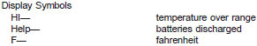
8.4.2 Temperature Indicator (Serial No. 378 and higher) - Be sure the ambient air thermocouple is in its operating position (pulled to the right toward the lamp) and the stack thermocouple is connected. The output switch must be in the "OFF" position. Place the power switch in the "F" ahrenheit position. No additional adjustment is required. Return power switch to the "OFF" position between tests to conserve batteries. (Note 6.)
8.4.2.1 Four type 1.2 AHR SC Size rechargeable batteries are used to supply power for the unit. To recharge the battery pack, insert the battery charger plug into the "RECHARGE" jack located on the front panel. Use the 115 volt charger only on a 115 volt line (Note 6).
NOTE 6 - For maximum battery life, it is recommended that the unit8 be charged only when the discharged battery indication (display indicates HELP) is observed. Do not charge for periods longer than 18 h. Charge unit before initial use.
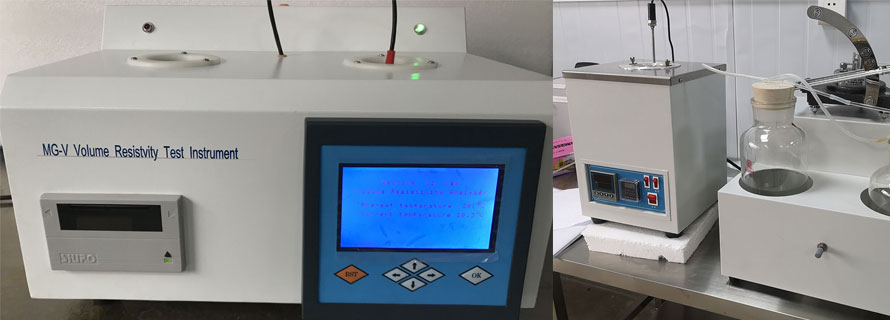
8.4.3 Digital Temperature Indicator (Serial No. 410 and Higher) - Be sure the ambient air thermocouple is in its operating position (fully extended to the lamp) and the stack thermocouple is connected. Turn unit on by pressing the On/Off position on front key pad. Input temperature will be displayed.
8.4.3.1 Battery is a standard 9 V to supply power for the unit.
8.5 Luminometer Meter - Turn the switch located below the right hand side of the luminometer meter to the OFF position. Adjust the meter to "0" by rotating the meter arm pivot screw on the lower front center of the meter. Then turn the switch to ZERO and turn the zeroing adjustment control located below the left-hand side of the meter until the meter arm rests at "0". To facilitate zeroing use the coarse and a fine zero adjustment. Next turn the switch to A1, A2, B1, and B2 to check the battery voltage. If on each switch position the meter rests above the appropriate mark on the meter scale, the batteries are satisfactory and the unit is ready for use. If the batteries are under strength, replace them. When replacing the "B" batteries also replace the photocell batteries located inside the photocell box.