ASTM D1266 Test Method for Sulfur in Petroleum Products (Lamp Method)
7. Preparation of Apparatus
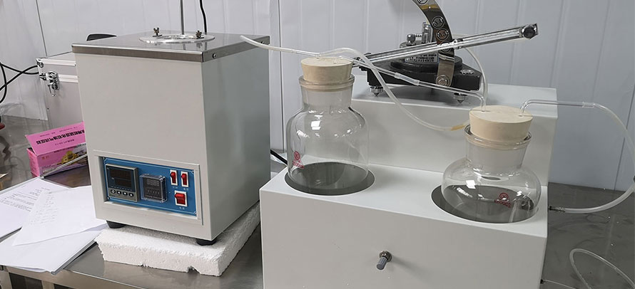
7.1 When the apparatus is first assembled, charge the absorber with 30 more or less 2 mL of water. Adjust the individual valves between the vacuum manifold and spray traps so that approximately 3 L of air per minute will be drawn through each absorber when the chimney outlets are open to the atmosphere, while maintaining the pressure in the vacuum manifold at approximately 40 cm of water below atmospheric. When all adjustments have been made, remove the water from the absorbers. The height of the liquids in the pressure and vacuum regulators is indicated in Fig. 2, and during operation a slow leak of gas should be maintained through them.
NOTE 4 - In use, place 300 to 400 mL of H2O2 solution (1 + 19) in the scrubber. Since the manifold manometer also serves as a scrubber at the end of the test to remove CO2 from the absorbent use H2O2 solution (1 + 19) as the manometric liquid. Replace weekly or whenever the volume becomes appreciably less than the original.
7.2 Neutralize the H2O2 solution (1 + 19) immediately before use. As 30 mL of the solution is needed, transfer to a beaker multiples of 30 mL sufficient for the number of absorbers to be used simultaneously. Add 1 drop of methyl purple indicator solution for each 100 mL of H2O2 solution and then add 0.05 N NaOH solution dropwise until the color changes from purple to light green.
7.3 Introduce 30 more or less 2 mL of the freshly neutralized H2O2 solution (1 + 19) into the larger bulb of each absorber. In addition, for each set of samples burned, prepare an extra absorber for use as a control blank. Attach the spray traps and chimneys and connect them to their respective manifolds by means of sulfur-free rubber tubing. Close the chimney openings by means of corks.
7.4 With the burner control valves closed, the valve to the vacuum regulator fully open, and the pressure in the vacuum manifold adjusted to approximately 40 cm of water below atmospheric, turn on the CO2 and O2 supplies (Warning - see Note 5). Adjust the chimney manifold control valve so that, at the required rate of flow through the absorbers, only a small stream of CO2-O2 gas escapes at the pressure regulator, a small stream of air enters at the vacuum regulator, and the pressure in the chimney manifold is 1 to 2 cm of water. Minor adjustment of the vacuum regulator and vacuum control valve may be necessary to achieve this condition (Note 6).
NOTE 5 - Warning: A hazardous (explosive) condition can result if the CO2 supply is interrupted and the O2 flow is continued while samples are being burned. The installation of suitable warning or control equipment is recommended.
NOTE 6 - It is convenient to balance the gas flow system by regulating the pressure in the vacuum manifold. This is done by raising or lowering the air inlet tube in the vacuum regulator by sliding it in a rubber sleeve.
7.5 Cut the wicking to 30-cm lengths. Use the number of lengths dictated by the sample (see Section 8); fold the wicking once to give a 15-cm long bundle for threading the burners. Thread the required number of burners by inserting the looped ends into the top of the inner tube of the burner. Draw the wicking through by means of a metal hook. Trim the wick as close as possible to the top of the burner with a pair of sharp scissors. It is essential that thoroughly cleaned burners and new wicking be used for each test.